
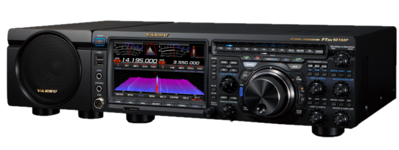
FTDX101MP 200W, FTDX101D 100W Direct SDR Transceiver for HF/6M
The FTDX101D and FTDX101MP are dual receiver Hybrid SDR transceivers that combine the large Dynamic Range of a Direct Sampling SDR with the super sensitivity and selectivity of a narrow band SDR. The FTDX101MP is the 200W version named in honour of Mr Sako Hasegawa JA1MP the founder of Yaesu Musen Co, and includes an AC PSU in the speaker box. The FTDX101D is the 100W version powered from suitable 13.8V owner supplied PSU. by 13.8VDC.
Features include:
2 seperate independent SDR receivers
4 Seperate Aerial inputs and 1 RX input. can be allocated to specific bands
400MHz HRDDS (High Resolution Direct Digital Synthesizer) with measureed 2KHz Phase noise of -150dBc/Hz or better
VC-TUNE (Variable Capacitor Tune) signal peaking
Multiple SDR noise reduction functions to pull the signal out of the noise
Includes Digital Processing Generated Real-Time Spectrum Scope
3DSS (3-Dimensional Spectrum Stream) visual display.
Hybrid SDR Configuration
In addition to the Narrow band SDR receiver, that boasts overwhelming Basic Performance, the Hybrid Configuration Digital Processing with Direct Sampling SDR permits inclusion of the superb Real-Time Spectrum Scope. *300Hz and 1.2kHz roofing filters (Optional)
Narrow band SDR
Crystal Roofing Filters produce phenomenal Multi-signal characteristics
The Down Conversion type receiver construction is similar to the FTDX5000. The first IF frequency is 9 MHz, and a low noise figure dual gate MOS FET, D-quad DBM (Double Balanced Mixer) with excellent intermodulation characteristics, is implemented in the mixer section. Narrow band SDR configuration makes it possible to use the narrow bandwidth crystal roofing filters that have the sharp shape factor. This achieves the amazing multi-signal receiving performance when confronted with the most challenging on-the-air interference situations.
In addition to IF down-conversion, The FTDX101 receivers implement the YAESU legendary powerful RF Front-Ends, outstanding low-noise Local Oscillators, roofing filters with sharp shape factors, and the latest circuit configurations that we carefully selected for all circuit elements. Consequently, the proximity BDR (Blocking Dynamic Range) in the 14 MHz band reaches 150 dB or more, the RMDR (Reciprocal Mixing Dynamic range) reaches 123 dB or more, and the 3rd IMDR (third-order Intermodulation Dynamic Range) reaches 110 dB or more.
Narrow Band SDR + Direct Sampling SDR
Emphasizes Excellent Receiver Performance and Hybrid SDR Functionality
Digital Processing Generated Real-Time Spectrum Scope
The Narrow band SDR receiver removes strong out of band signals by using a superheterodyne method, with narrow band roofing filters which significantly attenuates unwanted out of band frequency components, and the wanted signals within the passband are converted to digital by a high resolution 18-bit A/D converter and sent to an FPGA (Field Programmable Gate Array) for signal processing.
The FT DX 101 series uses a hybrid SDR configuration that integrates a direct sampling SDR receiver in order to view the entire band status in real time, with the excellent dynamic receiver performance achieved by the narrow band SDR receiver circuit.
By using this hybrid SDR design, the overall performance of the entire FTDX101 receiver system is improved. The Direct Sampling SDR driving the real time Spectrum display with its large dynamic range enables the weakest signal to be observed on the display when it appears and the Narrow Band SDR enables that signal to be selected, filtered and then decoded.
If there is powerful AM station near your location or in challenging operating situations where there are a lot of strong signals in the band from Contests, DX-pedition activities, those signals outside the pass band can be attenuated by the very effective roofing filter in the front stage of the A/D converter. This reduces the signal load on the A/D converter which is a bottleneck from the viewpoint of the entire receiving circuit. Therefore, interference is reduced making it is possible to continue to operate even under such difficult conditions.
Truly Quiet and Clear Reception
Ultra Low-Noise Local Oscillator System; 400MHz HRDDS (High Resolution Direct Digital Synthesizer)
The C/N ratio (signal-to-noise ratio) of the local signal injected into the 1st mixer is an important factor in improving the proximity multi-signal characteristics. The local circuit of the FTDX101 series uses the 400 MHz HRDDS (High Resolution Direct Digital Synthesizer) method that was used in the FTDX5000. This circuit configuration is different from a generic PLL that generates a local signal. Creating the local signal by directly dividing the high frequency of 400 MHz, the theoretical PLL lockup time becomes zero, and C/N deterioration by the lockup time does not occur.
The significant improvement of the C/N characteristic by directly dividing the frequency contributes dramatically to reduce the noise in the entire receiver stage, and also improve the BDR (Blocking Dynamic Range) characteristic in strong signals proximity.
In the FTDX 101 series, in addition to the adoption of the 400 MHz HRDDS, the latest circuit configurations that reduced noise, and carefully selected components are used. As a result, the phase noise characteristic of the local signal achieves an excellent value of -150 dBc/Hz or less at 2kHz separation.
This low-noise, high-quality local signal contributes significantly to the multi-signal and the ultra-close signal proximity (such as a few hundred hertz) characteristics.
Unparalleled -70 dB Maximum Attenuation VC-Tune
Newly developed VC-Tune RF Preselector with high precision stepping motor drive provides outstanding attenuation characteristics
Frequency automatic adjustment RF Preselector VC-Tune
In the FTDX101 series, a next-generation RF preselector VC-Tune further improves the high-performance RF μ (mu)-Tuning system adopted in FTDX9000. Using a remarkable miniaturization design while producing unparalleled characteristics and maximum attenuation of -70 dB.
Newly developed VC-tune circuit drives a variable capacitor (VC) with a high precision stepping motor and achieved remarkable miniaturization over μ-tuning system.
VC-Tune has no annoying steps or switching relays by continuously covering the band with a variable capacitor driven by a high-precision stepping motor following the frequency. The conventional preset method of switching coils and capacitors with relays is eliminated.
When there are multiple strong signals in the band, press the \”VC TUNE\” key and turn the MPVD (Multi-Purpose VFO Outer Dial) ring on the VFO dial to activate the high-precision stepping motor to adjust the variable capacitor. Fine tune to the optimum point that attenuates the strong signal in the band while operating the VFO dial.
VC-Tune stores the last tuning point for each band, so when broadcast-like signals are periodically transmitted on the same frequency, that frequency can always be attenuated by setting the VC-Tune once.
The Highest Transmit Signal Purity
High-Quality transmission with outstanding phase noise characteristics
Transmit Final Stage produces the Highest Signal Purity
The excellent C/N characteristics provided by the 400MHz HRDDS (High Resolution Direct Digital Synthesizer) used in the local oscillator circuit also contributes significantly to the transmitter section. In a generic circuit, noise or distortion may occur depending on the circuit configuration and the components, up to the final stage that is producing the transmit signal, even if the local signal is of high quality. In the FTDX101, a thorough examination of each element up to the final TX stage was made. The clock that divides and distributes the local signal from the 400MHz HRDDS circuit to each block, as well as the FPGA, D/A converter, the final power amplifier etc., and carefully selecting the latest circuit configurations to improve the C/N characteristics of the entire transmitter block. The transmit signal of the FTDX101 is directly generated from a 16-bit D/A converter without passing through a mixer circuit, therefore distortion and noise are significantly suppressed.
As a result, high-quality local signal characteristics are maintained without degradation to the final stage, and the transmission phase noise characteristics achieve -150 dBc/Hz at 2kHz separation. FTDX101 transceiver user will appreciate the finest performance with a high-purity transmission signal.
New Generation Scope Display 3DSS
Intuitively grasp changes in the strength of the signals
Newly developed 3DSS (3-Dimentional Spectrum Stream) system
in addition to a conventional Waterfall display
7-inch TFT Color Touch Panel Display
Size: 7-inch Wide
Resolution: 800 x 480 pixels
ABI (Active Band Indicator) & MPVD (Multi-Purpose VFO Outer Dial)
Deliver Superior Operability and Visibility plus Introduce Numerous Functions
Front Panel Design Emphasizes Solid Superior Touch and Operability
Primary important operation functions such as the Main VFO dial, VC-TUNE, WIDTH/SHIFT are arranged near the center of the pane for easy access.
Band select keys are placed as a row of ABI (active band indicator) at the top of the VFO dial, with your operating efficiency and comfort.
Even with a Large 7-inch Touch Panel Display, the panel layout emphasizes quick visibility and operability as a First Priority.
ABI (Active Band Indicator)
ABI is arranged as the band select key in the horizontal a row at the top of VFO dial.
When the band selected as MAIN Band, the LED indicates in white, and when the band selected by SUB band, the LED indicates in blue. At the status of transmission, the LED turns red so you can instantly confirm which VFO is transmitting.
In addition, since the orange LED lights up when you press and hold the band key, you can use it to display a band that has an antenna connected or to display a band operated in DX-pedition mode as a memo. Below the band key is a key for selection between transmission and reception of the MAIN and SUB band, and below that, there is a switching key for using the VFO knob on the MAIN or SUB tuning, so, even when the operating split using both MAIN and SUB bands at the same time, the band control can be performed smoothly, and so tuning the wrong band by mistake is reduced.
MPVD (Multi-Purpose VFO Outer Dial)
The MPVD is a large high-grade aluminium multifunctional ring around the outside of the VFO dial. The ring allows control of SUB VFO frequency dial, VC-TUNE, Clarifier and C/S (custom select function). The MPVD is a handy dial that allows you to adjust important functions in ever-changing HF communications without taking your hand off the VFO. The ring has the traditional Yaesu outstanding smooth and solid feeling when used.
Specifications
| General | ||
| TX Frequency Range | 1.8 MHz – 50MHz Band | |
| RX Frequency Range | 30KHz – 75MHz | |
| 1.8MHz – 29.6999MHz | (Specified performance, Amateur bands only) | |
| 50.0MHz – 53.9999MHz | (Specified performance, Amateur bands only) | |
| 70.0MHz – 70.4999MHz | (Specified performance, UK Amateur bands only) | |
| Emission Modes | A1A (CW), A3E(AM), J3E (LSB/USB), F3E (FM), F1B (RTTY),G1B (PSK) | |
| Frequency Steps | 1/5/10Hz (SSB,CW) 10/100Hz (AM/FM) | |
| Antenna Impedeance | 50Ω unbalanced Tuner OFF 16.7Ω – 150Ω unbalanced (1.8MHz – 29.7MHz 25.0Ω – 199Ω unbalanced (50MHz) | |
| Operating Temperature Range | +32ºF to +122ºF (0ºC to +50ºC) | |
| Frequency Stability | ±0.1ppm (after 1 minute @ +14F to 140ºF [-10ºC to +60ºC]) | |
| Supply Voltage | AC 100V – 240V (FTDX101MP) DC 13.8V ±10% (FTDX101D) | |
| Power Consumption (Approx) | RX Signal present – 120VA (FTDX101MP), 4.0A (FTDX101D) TX 720VA (FTDX101MP : 200W) TX 23A (FTDX101D : 100W) | |
| Dimensions | 420mm x 130mm x 322mm 16.6″ x 5.1″ x 12.7″ | |
| Weight | FTdx101MP 28.8lbs 13.5Kg FTdx101D 26.5lBs 12.0Kg | |
| TRANSMITTER | ||
| Power Output | FTDX101MP 200W CW/SSB 50W AM FTdx101D 100W CW/SSB 50W AM | |
| Modulation Types | J3E SSB balanced A3E AM low level early stages F3E FM Variable Reactance | |
| Maximum FM Deviation | ±5KHz or±2.5KHz Narrow | |
| Harmonic Radiation | => -50dB 1.8 – 29.7MHz Amateur bands only => -66dB 50MHz Amateur Band 200W => -63dB 50MHz Amateur Band 100W | |
| SSB Carrier Suppression | At least 60dB below peak output | |
| Undesired Sideband suppression | At least 69dB below peak output | |
| Bandwidth | 3KHz (LSB/USB) 500Hz CW | |
| Audio Response (SSB) | Not more than -6dB from 300 – 2700Hz | |
| Microphone Impedance | 600Ω (200 – 10KΩ) data input | |
| RECEIVER | ||
| Circuit Type | Double Superhetrodyne | |
| Intermediate Frequencies | 1st IF 9.0005MHz (MAIN) 8.9000MHz (SUB) 2nd IF 24HKz Main and Sub | |
| Sensitivity | ||
| SSB/CW (BW 2.4KHz/10dB S+N/N) | SSB/CW (BW 2.4KHz/10dB S+N/N) 1.8MHz – 30.0MHz 0.16uV (AMP2 ON) | |
| 50MHz – 54MHz | 0.125µV (AMP2 ON) | |
| 70MHz – 70.5MHz | 0.16µV (AMP2 ON) | |
| AM (BW: 6KHz/10dB S+N/N 30% Modulation @ 400 Hz | 0.5MHz – 1.8MHz 6.0uV | |
| 1.8MHz – 30MHz | 2.0µV (AMP2 ON)) | |
| 50MHz – 54MHz | 1.0µV (AMP2 ON) | |
| 70MHz – 70.5MHz | 2.0µV (AMP2 ON) | |
| FM (BW:12KHz 12dB SINAD) | s0.25µV (AMP2 ON) | |
| 50Mhz – 54MHz | 0.2µV (AMP2 ON) | |
| 70MHz – 70.5MHz | 0.25µV (AMP2 ON) | |
| Selectivity (Width Centre) | -6dB -60dB | -60dB |
| CW (BW=0.5KHz) | >0.5KHz 0.75KHz or less | 0.75KHz or less |
| SSB (BW=2.4KHz) | >2.4KHz 3.6KHz or less | 3.6KHz or less |
| AM (BW=6KHz) | >6KHz 15KHz or less | 15.0KHz or less |
| FM (BW=12KHz) | >12KHz 25KHz or less | 25KHz or less |
| Image Rejection | >0.5KHz 0.75KHz or less | 60dB or better (50Mhz – 54 MHz Amateur Bands ) |
| Maximium Audio Output | 2.5W into 4Ω load with 10% THD | |
| Audio Output Impedance | 4Ω to 16Ω ( 4Ω Nominal ) | |
| Conducted Radiation | Less than 4nW | |
| FTDX101 Series Standard Equipment | ||
| FTDX101MP | FTDX101D | |
| Transmitter Power | 200W | 100W |
| Supply Voltage | AC 100/20V FPS101 External Power Supply with Speaker SP-101 included | DC 13.8V Power Cord Supplied |
| External Speaker | Built into FPS-101 Power Supply | Option (SP10) |
| VC-Tune Unit (MAIN) | Fitted as Standard | Fitted as Standard |
| VC-Tune Unit (SUB) | Fitted as Standard | Option (VCT-101) |
| CW Filter 600Hz | Fitted as Standard for MAIN and SUB | Fitted as Standard for MAIN and SUB |
| CW Filter 300Hz | Fitted as Standard for MAIN (9.005MHz) Option for SUB XF-129CN (8.9000MHz) | Option for MAIN XF-128CN (9.005MHz)** Option for SUB XF-129CN (8.900 MHz)** |
| SSB Filter 3.0KHz | Fitted as Standard for MAIN and SUB | Fitted as Standard for MAIN and SUB |
| SSB Filter 1.2KHz | Option for MAIN XF-128SN (9.005MHz) Option for SUB XF-129SN (8.900MHz) | Option for MAIN XF-128SN (9.000MHz) Option for SUB XF-129SN (8.900MHz) |
| AM Filtr 12KHz | Fitted as Standard for MAIN and SUB | Fitted as Standard for MAIN and SUB |
| ** Dealer fit only |
Supplied Accessories
| FTDX101D 100W | FTDX101MP 200W |
| 100W Transceiver | 200WTransceiver |
| SSM-75G Hand Microphone | SSM-75G Hand Micrphone |
| DC Powe Cable | FPS101 PSU with Speaker |
| Spare DC Fuses, 2 X RCA Jacks 3.5mm and 6.3mm Jack plugs | Spare DC Fuses, 2 x RCA Jacks 3.5mm and 6.3mm Jack Plugs |
| FTDX101D User Manual | FTDX101MP User Manual |
| World Map | World Map |
| Yaesu Sticker | Yaesu Sticker |
| Circuit Diagrams | Circuit Diagrams |
We believe that hearing a weak target signal in an environment of close strong interference is the most important feat required of HF DX communications equipment in every era. Raising and meeting this goal is the ultimate mission that Yaesu has challenged for over 60 years. Named after the well-known FT-101, a corner stone in the history of HF Transceivers, the FTDX101MP introduces the future of HF Communications and is named in honour of the founder of Yaesu Mr Sako Hasegawa JA1MP provides 200W TX power on the HF, 6M bands and 4M for those countries who allow 70MHz operation. The FTdx101MP includes the new VC-Tune option on both Main and Sub Receivers and the Optional narrow CW Roofing filters for both Main and Sub Receiver. The Narrow SSB filters are available as an option.